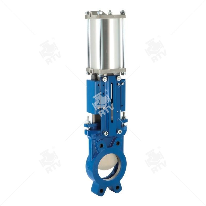
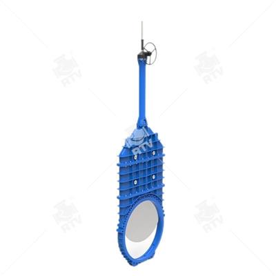
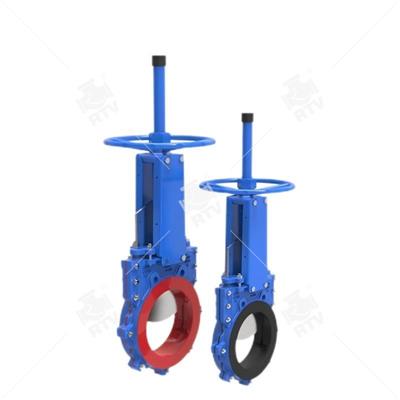
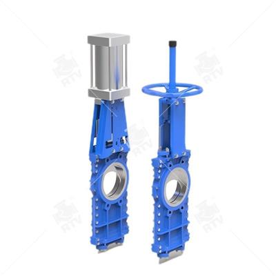
Produced by Ruitong Valve Knife gate valve The opening and closing part of the knife gate valve is the ram, and the movement direction of the gate is perpendicular to the direction of the fluid. The knife gate valve can only be fully opened and closed, and can not be adjusted and throttled. The gate has two sealing surfaces. The two sealing surfaces of the most commonly used mode gate valves form wedges and wedge angles that vary with the parameters of the valve, usually 50. The sluice of the wedge type knife gate valve can be made into a whole, called a rigid gate, and a sluice which can produce a trace deformation to improve its craft and make up the angle of the seal face. Deviations produced in the process of work.
Technical Specification
Normal Size Range: 2"-60"
Normal Pressure Rating: PN10~PN16, CLASS150
Material: GG25,GG40,WCB, CF8,CF8M,CF3,CF3M
Operation: Handwheel, Pneumatic, Electric, Chainwheel. Lever
Seat: EPDM, Viton, Metal, PTFE, NBR
Temperature Range: -29~150Degree C
Standards compliance
Design and Manufacture: GB/T12237
Face to face(end to end): GB/T15188.2
Flanged connection: ANSI B16.5, GB/T 9113
Test and inspection: API 598, GB/T 13927
RTV-Valve Figures C37 and F37 are some of the most popular knife gate valve configurations. Figure C37 knife gate valves through 24”, feature a heavy duty, rugged one-piece cast body, chest and flanges (except 5”, which is fabricated – F37). Sizes larger than 24” are fabricated from heavy plate.
The Figure C/F37 is available in all stainless steel (designated “S”) or with alloy steel wetted parts and carbon steel external parts (designated “R”). In sizes 1.5” through 24”, the “S” and the “R” share the same solid cast body. Sizes larger than 24” feature fabricated bodies configured to the service conditions.
The Figure C/F37 is available with the widest range of seats in the industry including: integral metal, replaceable hardfaced metal, rubber “D” ring, replaceable rubber, polyurethane, UHMW-P, and PTFE. Standard body materials include 304, 316, and 317L stainless steel. Special alloys such as 254 SMO® are also available. Special flange drillings are also available.
FEATURES AND BENEFITS
- “D” Ring Seat
• Lever Operator
• Dual Seats
• Poly Replaceable Seats
• UHMW Replaceable Seats
• PTFE Replaceable Seats
• Rubber Replaceable Seats
• Hard Faced Replaceable Seats
• Elastomer Replaceable Seats
• Hard Faced Gate Edge
• Hard Gate Material
• Nickel-TFE Coated Gate
• Epoxy Coating
• Thru Drilled Flanges
• Flush Ports
• Chest Buttons: Not available 2”-6”
• Centerline Buttons
• Backing Ring
• Extra Wedges
• V-Port
• Cast Ni-Hard Deflection Cones available 3”-16”
• Fabricated Deflection Cones
• Locking Devices
• Live Loaded Packing
• Self-Supporting Yokes
• Alternate Flange Drilling
• Bevel Gear
• Chainwheels
• Cylinder Actuators
• Electric Actuators
• Ratchet
• Extended Stems
• Gate Support Strips
• Rod Boots
Pneumatic Knife Gates
|
Size |
A |
B |
C |
D |
E |
F |
G |
H |
Weight |
|
2 |
2 |
1 7/8 |
3 |
16 1/4 |
4 1/2 |
4 |
5/8 UNC |
4 3/4 |
23 LBS |
|
4 |
4 |
2 |
4 3/8 |
22 |
4 1/2 |
8 |
5/8 UNC |
7 1/2 |
33 LBS |
|
6 |
6 |
2 1/4 |
5 3/8 |
27 1/2 |
5 1/2 |
8 |
3/4 UNC |
9 1/2 |
60 LBS |
|
8 |
8 |
2 3/4 |
6 5/8 |
34 1/4 |
6 7/8 |
8 |
3/4 UNC |
11 3/4 |
105 LBS |
|
10 |
10 |
2 3/4 |
8 |
39 5/8 |
8 5/8 |
12 |
7/8 UNC |
14 1/4 |
155 LBS |
|
12 |
12 |
3 |
9 3/8 |
45 |
8 5/8 |
12 |
7/8 UNC |
17 |
200 LBS |
|
14 |
14 |
3 |
10 1/4 |
51 |
10 7/8 |
12 |
1 UNC |
18 3/4 |
300 LBS |
|
16 |
16 |
3 1/2 |
11 1/2 |
56 |
10 7/8 |
16 |
1 UNC |
21 1/4 |
360 LBS |
|
18 |
18 |
3 1/2 |
12 3/8 |
65 |
15 |
16 |
1 1/8 UNC |
22 3/4 |
470 LBS |
|
20 |
20 |
4 1/2 |
13 1/2 |
70 |
15 |
20 |
1 1/8 UNC |
25 |
645 LBS |
|
24 |
24 |
4 1/2 |
15 3/4 |
79 1/2 |
15 |
20 |
1 1/4 UNC |
29 1/2 |
830 LBS |
Manual Knife Gate
|
Size |
A |
B |
C |
D |
E |
F |
G |
H |
Weight |
|
2 |
2 |
1 7/8 |
3 |
16 1/2 |
8 7/8 |
4 |
5/8 UNC |
4 3/4 |
18 LBS |
|
4 |
4 |
2 |
4 3/8 |
20 3/8 |
8 7/8 |
8 |
5/8 UNC |
7 1/2 |
28 LBS |
|
6 |
6 |
2 1/4 |
5 3/8 |
25 1/4 |
8 7/8 |
8 |
3/4 UNC |
9 1/2 |
45 LBS |
|
8 |
8 |
2 3/4 |
6 5/8 |
32 1/4 |
12 1/4 |
8 |
3/4 UNC |
11 3/4 |
75 LBS |
|
10 |
10 |
2 3/4 |
8 |
38 7/8 |
12 1/4 |
12 |
7/8 UNC |
14 1/4 |
105 LBS |
|
12 |
12 |
3 |
9 3/8 |
42 1/8 |
16 1/8 |
12 |
7/8 UNC |
17 |
145 LBS |
|
14 |
14 |
3 |
10 1/4 |
49 |
16 1/8 |
12 |
1 UNC |
18 3/4 |
215 LBS |
|
16 |
16 |
3 1/2 |
11 1/2 |
52 1/8 |
16 1/8 |
16 |
1 UNC |
21 1/4 |
270 LBS |
|
18 |
18 |
3 1/2 |
12 3/8 |
59 1/2 |
21 5/8 |
16 |
1 1/8 UNC |
22 3/4 |
355 LBS |
|
20 |
20 |
4 1/2 |
13 1/2 |
63 5/8 |
21 5/8 |
20 |
1 1/8 UNC |
25 |
445 LBS |
|
24 |
24 |
4 1/2 |
15 3/4 |
74 1/8 |
21 5/8 |
20 |
1 1/4 UNC |
29 1/2 |
640 LBS |


